• Science knowledge about solar pv power generation Science knowledge about solar pv power generation Oct 10, 2023
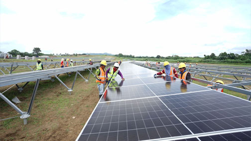
    1. What is photovoltaic power generation? Photovoltaic power generation refers to a power generation method that uses solar radiation to directly convert into electrical energy. Photovoltaic power generation is the mainstream of solar power generation today. Therefore, what people often call solar power generation now is photovoltaic power generation.   2. Do you know the historical origin of photovoltaic power generation? In 1839, 19-year-old Becquerel of France discovered the "photovoltaic effect" while doing physical experiments when he discovered that the current would increase when two metal electrodes in a conductive liquid were irradiated with light. In 1930, Lange first proposed using the "photovoltaic effect" to manufacture solar cells to turn solar energy into electrical energy. In 1932 Odubot and Stola made the first "cadmium sulfide" solar cell. In 1941 Audu discovered the photovoltaic effect on silicon. In May 1954, Chapin, Fuller and Pierson of Bell Labs in the United States launched a monocrystalline silicon solar cell with an efficiency of 6%. This was the first solar cell with practical value in the world. In the same year, Wick first discovered the photovoltaic effect of nickel arsenide, and deposited a nickel sulfide film on glass to create a solar cell. Practical photovoltaic power generation technology that converts sunlight into electrical energy was born and developed.   3. How do photovoltaic solar cell generate electricity? Photovoltaic solar cell is a semiconductor device with light and electricity conversion characteristics. It directly converts solar radiation energy into direct current. It is the most basic unit of photovoltaic power generation. The unique electrical characteristics of photovoltaic cells are achieved by incorporating certain elements into crystalline silicon. Elements (such as phosphorus or boron, etc.), thereby causing a permanent imbalance in the molecular charge of the material, forming a semiconductor material with special electrical properties. Free charges can be generated in semiconductors with special electrical properties under sunlight. These free charges Directional movement and accumulation, thus generating electrical energy when its two ends are closed, this phenomenon is called the "photovoltaic effect"   4. What components does a photovoltaic power generation system consist of? The photovoltaic power generation system consists of a solar panel array, a controller, a battery pack, a DC/AC inverter, etc. The core component of the photovoltaic power generation system is solar panel, It is composed of photovoltaic solar cells connected in series, parallel and packaged. It converts the sun's light energy directly into electrical energy. The electricity generated by solar panel is direct current. We can use it or use an inverter to convert it into alternating current for use. From one perspective, the electric energy generated by the photovoltaic solar system can be used immediately, or the electric energy can be stored using energy storage devices such as batteries and released for use at any time as needed.
  • How to improve the power generation efficiency of solar stations? How to improve the power generation efficiency of solar stations? Sep 26, 2023
    There are many factors that affect the power generation and efficiency of a solar station with the same capacity. Today SAIL SOLAR will lead you to have a studying.   1. Solar Radiation When the conversion efficiency of solar panel is constant, the power generation of the solar system is determined by the intensity of solar radiation. Normally, the utilization efficiency of solar radiation by solar systems is only about 10%. Therefore, solar radiation intensity, spectral characteristics, and climate conditions must be taken into consideration. If the current year's power generation exceeds or falls short of the standard, it is likely that the overall solar radiation for that year deviates from the average.   2. Tilt angle of solar panel The azimuth angle of solar panel is generally selected in the south direction to maximize the power generation per unit capacity of solar station. As long as it is within ±20° of due south, it will not have much impact on the power generation. If conditions permit, it should be as far as 20° to the southwest. The above angle recommendations are based on installation in the Northern Hemisphere, and vice versa for the Southern Hemisphere. Tilt angles vary from place to place, and local installers are more familiar with the optimal tilt angle for components. If it is a pitched roof, in order to save brackets, many of them will be laid flat on the roof, regardless of the tilt angle, for the sake of beauty.   3. Solar panel efficiency and quality There are many solar panel types to choose from on the market, such as polycrystalline silicon, monocrystalline silicon solar panel, etc. Different solar panels have different power generation efficiency, attenuation and quality. The most important thing is must purchase them from regular channels at a reasonable market price. Only in this way can you ensure stable and reliable power generation for 25 years.   4. Solar panel matching loss Any series connection will cause current loss due to the current difference of solar panels, and any parallel connection will cause voltage loss due to the voltage difference of solar panels. Losses may reach more than 8%. In order to reduce the matching loss and increase the power generation capacity of the solar  station, we should pay attention to the following aspects: 1)To reduce matching losses, try to use solar panels with consistent current in series; 2)The attenuation of solar panels should be kept as consistent as possible; 3)Isolation diode.   5. Temperature (ventilation) Data shows that when the temperature rises by 1°C, the output power of crystalline silicon solar panel decreases by 0.04%. Therefore, it is necessary to avoid the impact of temperature on power generation and maintain good ventilation conditions for the solar panels.    6. Effect of dust The crystalline silicon solar panel is made of tempered glass. If it is exposed to the air for a long time, organic matter and a large amount of dust will naturally accumulate. Dust falling on the surface blocks the light, which will reduce the output efficiency of the solar panels and directly affect the power generation. At the same time, it may also cause a "hot spot" effect on the solar panels, causing damage to the components. solar panel station must be cleaned in time.   7.Shadows, snow cover During the site selection process of the solar solution, attention must be paid to the light shielding. Avoid areas where light may be blocked. According to the circuit principle, when solar panels are connected in series, the current is determined by the smallest solar panels Therefore, if there is a shadow on one solar panels, it will affect the power generation of this solar panels. Therefore, when installing a solar power station, you must not be greedy for large capacity. You must consider the area of the roof and whether there is any obstruction around the roof.   8. Maximum output power tracking (MPPT) MPPT efficiency is a key factor in determining the power generation of solar inverters, and its importance far exceeds the efficiency of the solar inverter itself. MPPT efficiency is equal to hardware efficiency times software efficiency. Hardware efficiency is mainly determined by the accuracy of the current sensor and the accuracy of the sampling circuit; software efficiency is determined by the sampling frequency. There are many ways to implement MPPT, but no matter which method is used, the solar panel power changes must first be measured and then react to the changes. The key component here is the current sensor. Its accuracy and linear error will directly determine the hard efficiency, and the sampling frequency of the software is also determined by the accuracy of the hardware.   9. Reduce line losses In solar systems, cables account for a small part, but the impact of cables on power generation cannot be ignored. It is recommended that the line loss of the system's DC and AC loops be controlled within 5%. The cables in the system must be well prepared, including the insulation performance of the cable, the heat-resistant and flame-retardant performance of the cable, the moisture-proof and light-proof performance of the cable, the type of cable core, and the size and specification of the cable. Therefore, in daily operation and maintenance, we need to check whether the lines are damaged and whether there is leakage or other conditions. Especially after every typhoon or hailstorm, it is essential to check whether the lines and connectors are loose.   10. Inverter efficiency The solar inverter is the main component and important component of the solar system. In order to ensure the normal operation of the power station, the correct configuration and selection of the inverter is particularly important. In addition to the various technical indicators of the entire solar power generation system and the product sample manual provided by the manufacturer, the configuration of the inverter generally needs to consider the following technical indicators: 1. Rated output power 2. Output voltage adjustment performance 3,Overall machine efficiency 4.Start-up performance. There are not many daily environments that affect the efficiency of the inverter. Pay attention to installing the inverter in a cool place and keep the surroundings ventilated to facilitate the heat dissipation of the inverter. Especially in summer and autumn, normal heat dissipation can maintain the power generation efficiency of the inverter.
  • How photovoltaic power station to cope with the rainy season? How photovoltaic power station to cope with the rainy season? Aug 23, 2023
    With rainy season coming, the weather will become increasingly hot and humid. For photovoltaic power plants, on the one hand, the peak period of power generation is ushered in; on the other hand, the fluctuating temperature and frequent thunderstorms also pose a lot of challenges to the safe and efficient operation of the power plant. Take you from the following Starting from several aspects, learn more about the precautions for photovoltaic power plants: 1. Anti-high temperature 2. Anti-storm 3. Anti-lightning   1. How to prevent high temperature? Ensure air flow: ensure smooth air circulation around the inverter. Do not install the inverter in a narrow and closed environment. If multiple inverters are installed on the same plane, it is necessary to ensure that there is enough space between This not only ensures the ventilation and heat dissipation of the inverter, but also has enough operating space for later maintenance.   Avoid wind and sun: Although the protection level of our inverter meets the requirements for long-term use in outdoor environments, reducing the chance of the inverter being exposed to wind, sun, and rain can prolong the service life of the inverter. When installing the inverter, you can choose to install it at the bottom of the module or under the eaves. If the inverter is installed outdoors, it is recommended to install an awning at the same time, which can not only provide shelter from wind and rain, but also reduce direct sunlight, reduce the temperature of the inverter, avoid load reduction caused by overheating of the inverter, and ensure power generation efficiency.   2. How to prevent heavy rain? Rainstorms are frequent in summer, and the main impact on photovoltaic power plants is that a large amount of rainwater soaks cables and components, and the insulation performance is degraded or even damaged, causing the inverter to detect a fault and fail to generate electricity.   The sloping roof itself has strong drainage capacity, and generally there will be no excessive water accumulation; if the lower edge of the module is low on the flat roof, it may be soaked by rainwater; for photovoltaic power plants installed on the ground, rainwater washing the ground may cause module imbalance .   If the roof where the photovoltaic power station is installed is a sloping roof, there is basically no need to worry about heavy rain. If it is a flat roof, it is best to consider the drainage problem during the design and installation of the photovoltaic power station. It should be avoided that the photovoltaic modules are soaked by rainwater due to the relatively low bracket installation of the flat roof when the rainfall is too heavy.   Specific measures to prevent rainstorms in power stations: a. When designing a power station, geographical and geological factors should be taken into consideration, such as the orientation of the selected terrain, the degree of slope fluctuation, hidden dangers of geological disasters, depth of accumulated water, flood water level, drainage conditions, etc. b. For the power stations that have already been built, scientifically add drainage systems. Note: During inspection and maintenance in rainy days, avoid bare-handed electrical operations and do not directly touch the inverter, components, cables and terminals with your hands. You need to wear rubber gloves and rubber boots to reduce the risk of electric shock.   3. How to prevent from lightning? For the lightning protection of photovoltaic power stations, in addition to the conventional protective grounding on the component side, support side and distribution box side, the inverter, as the core electrical equipment of the photovoltaic power station, should also be well protected against lightning protection. Electrical grounding and protective grounding for protection.   Electrical grounding: Generally, the electrical grounding will be connected to the PE row of the electric box, and then grounded through the distribution box. The electrical grounding point is generally located at the AC terminal of the inverter, and there is a PE ( Ground) symbol identification.   Protective grounding: The inverter body has a grounding hole for grounding to protect the safety of the inverter and operators. The protective grounding point of the inverter is located on the body of the inverter and has a grounding mark. It is generally recommended to only connect to the protective ground (because lightning current discharge, faults and static electricity all go to the protective ground).   Protection against direct lightning strikes: set up metal lightning protection grounding conductors on tall buildings, including lightning rods, lightning protection belts, and grounding devices, which can release the huge thunderstorm cloud charge. All electrical equipment in the photovoltaic system cannot protect against direct lightning strikes.   Inductive lightning protection: Photovoltaic systems have lightning protection modules in electrical equipment such as combiner boxes and inverters to protect against indirect lightning strikes. The inverter has two levels of lightning protection and three levels of lightning protection. The second level of lightning protection uses lightning protection modules, which are generally used in medium and large photovoltaic power plants. There are no tall buildings around the power station. The third level of lightning protection uses lightning protection devices. It is used for household small-scale photovoltaic power plants, and there are tall buildings around the power plant.   The photovoltaic power generation system is equipped with lightning protection devices, and the Deye inverter has a built-in secondary lightning protection module, so it does not need to be disconnected in normal lightning weather. If there is a strong thunderstorm, for safety reasons, it is recommended to disconnect the DC switch of the inverter or the combiner box, and cut off the circuit connection with the photovoltaic module to avoid damage caused by induced lightning.
  • Cable Selection for Photovoltaic Power Station Cable Selection for Photovoltaic Power Station Aug 11, 2023
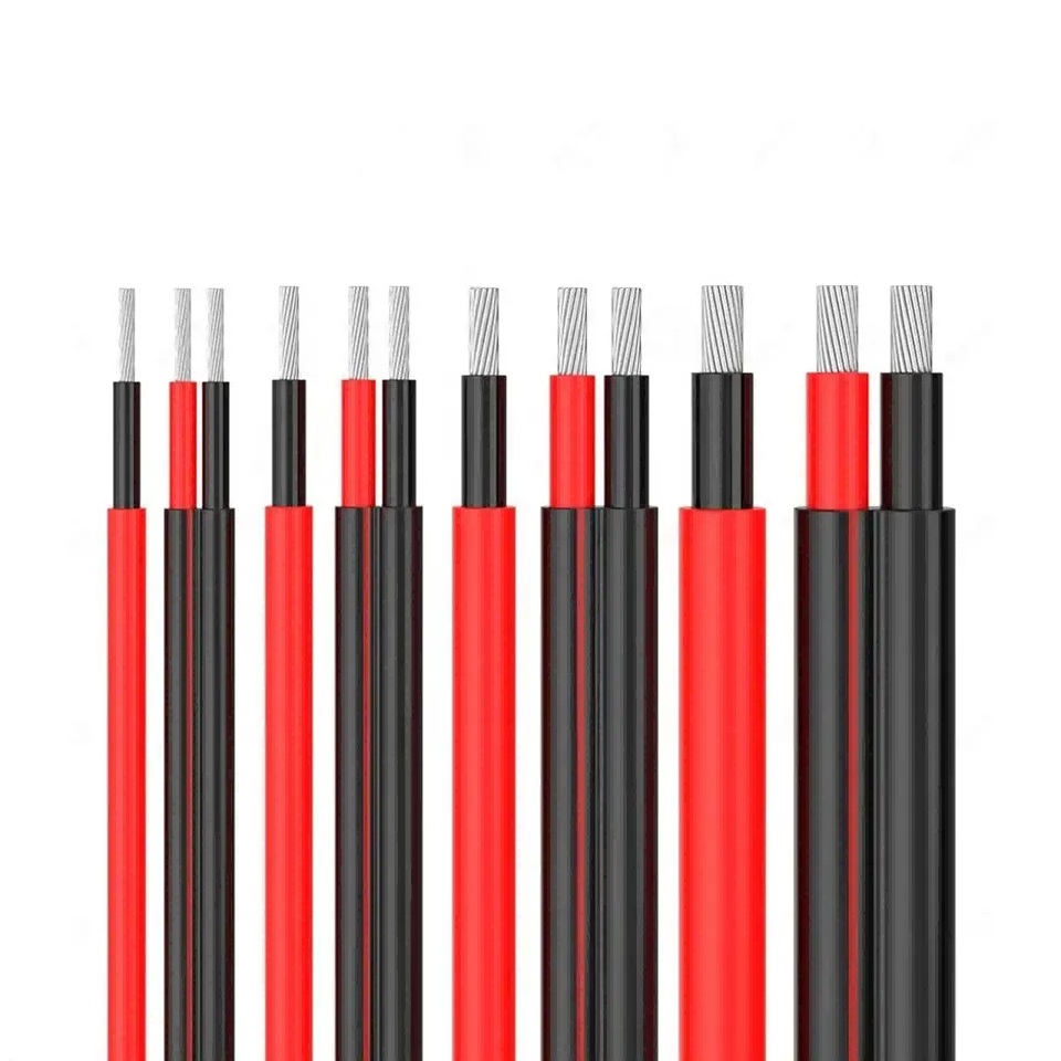
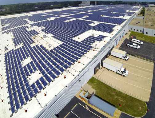
    In solar system, though the cost of the cable is not high, as the "blood vessel" of the pv system, it plays an important role in connecting pv modules, inverters, distribution boxes and the grid, and also plays an important role in the operation safety of the whole system, which even influences the overall profitability of the power station. Therefore, the cable selection in system design process is very critical.   1. Types of pv cables From the perspective of different functions, the cables in the pv system can be mainly divided into two types: DC cables and AC cables.   1.1 DC cable ① Serial cables between pv modules. ② Parallel cables between strings and between strings and DC distribution box (combiner box). ③ Cables between the DC distribution box and the inverter. The above cables are all DC cables, and they are often laid outdoors. They need to be protected from moisture, sun exposure, cold, heat, and ultraviolet rays. In some special environments, they also need to be resistant to chemical substances such as acids and alkalis.   1.2 AC cable ① Connecting cables from the inverter to the step-up transformer. ② Connecting cables from the step-up transformer to the power distribution unit ③ Connecting cables from the power distribution device to the power grid or users The above cables are all AC load cable, which are often laid in the indoor environment, and can be selected according to the general power cable selection requirements.   2. Why choose dedicated pv cable? Under much circumstance, DC cables need to be laid outdoors. The cable materials should be determined according to the resistance to ultraviolet rays, ozone, severe temperature changes and chemical erosion. The long-term use of ordinary material cables in this environment will cause the cable sheath to break and even decompose the cable insulation layer. These conditions will directly damage the cable system, and will also increase the risk of system short circuit. In the medium and long term, the possibility of fire or personal injury is also higher, which greatly affects the lifespan of the system. Therefore, it is very necessary to use dedicate pv cables and modules. Solar-specific cables and modules not only have the best weather resistance, UV and ozone resistance, but also can withstand a wider range of temperature changes.   3. Principles of cable design and selection ① The withstand voltage of the cable should be greater than the maximum voltage of the system. For example, for AC cables with 380V output, 450/750V cables would be selected. ② For the connection inside and between the system arrays, the rated current of the selected cable is 1.56 times the maximum continuous current in the calculated cable. ③ For the connection of AC loads, the rated current of the selected cable is 1.25 times of the calculated maximum continuous current in the cable. ④ For the connection of the inverter, the rated current of the selected cable is 1.25 times of the calculated maximum continuous current in the cable. ⑤ Consider the influence of temperature on the performance of cable. The higher the temperature, the less the current carrying capacity of the cable, and the cable should be installed in a ventilated and heat-dissipating place as much as possible. ⑥ Consider that the voltage drop should not exceed 2%.   4. The DC circuit is often affected by various unfavorable factors during operation and causes grounding, which makes the system unable to work. Such as extrusion, poor cable manufacturing, unqualified insulation materials, low insulation performance, DC system insulation aging, or some damage defects, can cause ground faults or become a grounding hazard. In addition, the intrusion or biting of wild animals in the outdoor environment will also cause a DC ground fault. In this case, armored cables with rodent-proof functional sheaths are generally necessary.   5. Summary: Select the appropriate cable according to the grid form supported by inverter and data of the maximum continuous current in the cable.
  • What is a anti-backflow? How to anti-backflow? Aug 04, 2023
    In a power system, power is generally sent from the grid to the load, which is called forward current. After installing a photovoltaic power station, when the power of the pv system is greater than that of the load, the power that cannot be consumed will be sent to the grid. Since the current direction is opposite to the conventional one, it is called “countercurrent".   1. What is anti-backflow? An usual photovoltaic power generation system converts AC to DC. When the power of the photovoltaic system is greater than that of local load, the extra electricity will be sent to the grid. The photovoltaic system with CT(Current Transformer) has anti-backflow function, which means that the electricity generated by photovoltaics is only supplied to loads, preventing excess electricity from being sent to the grid.   2. Why do you need anti-backflow? There are several reasons for installing an anti-backflow prevention solution: 2.1.Limited by the capacity of the upper-level transformer, users have new grid system installation needs, but it is not allowed locally. 2.2.Due to some regional policies, grid connection is not allowed. Once it is found, the grid company will impose a fine. 2.3.The pv panels have been installed, but due to incomplete filing information (such as unclear real estate property rights, etc.), the grid company does not allow grid connection, and the cost of installing energy storage systems is very high.   3. How to achieve anti-backflow? Install an meter or a current sensor at the grid-connected point, and feed back the detected grid access point data to the inverter. When it detects that there is current flowing to the grid, the inverter responds quickly and reduces the output power until the countercurrent is Zero, so as to achieve zero power Internet access.   4. The solution? Deye inverter anti-backflow working principle: install an meter with CT or current sensor at the grid-connected point. When it detects that there is current flowing to the grid, it will feed back to the inverter, and the inverter will immediately change its working mode and track from the maximum power point of MPPT. The working mode is transferred to the control output power working mode, and the output power of the inverter is nearly equal to the load side, so as to realize the anti-backflow function. According to different system voltage levels, photovoltaic anti-backflow systems can be divided into single-phase anti-backflow systems, three-phase and energy storage system ones.
  • The difference between solar panel efficiency and solar cell efficiency The difference between solar panel efficiency and solar cell efficiency Jun 09, 2023
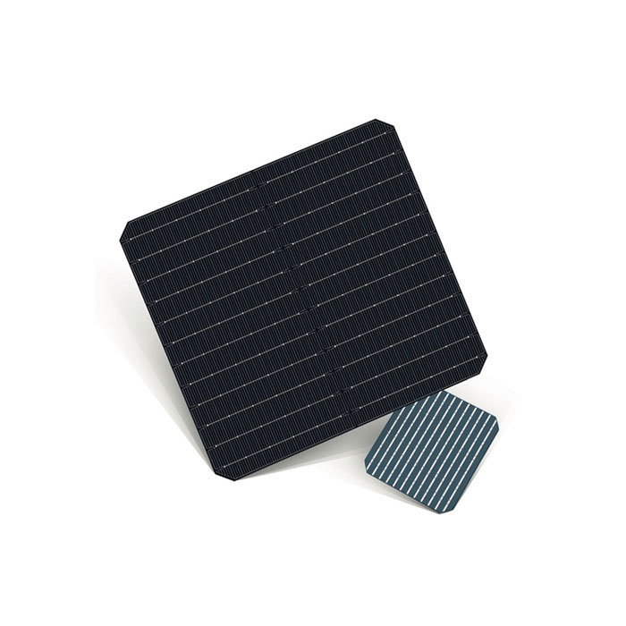
    How to calculate solar panel efficiency?   Let us take the SAIL SOLAR 550W solar panel as an example and calculate the module efficiency. PV module power (Pmax in watts) ÷ PV module surface area in square meters = 550W / (2.279m * 1.134m) / 1000 =21.3%   What is solar cell efficiency? Solar cell efficiency refers to the energy efficiency with which a solar cell converts it into electricity through photovoltaic technology. Also take the SAIL SOLAR 550W as an example. SAIL SOLAR 550W is made of 182mm solar cell ( dimension: 182*91mm). 144cells. 550W/144=3.82W per cell 3.82W/(0.182m*0.091m)/1000= 23.1%   Why is there a difference between solar panel efficiency and solar cell efficiency? Compared to the example of the SAIL SOLAR 550W mentioned above, solar cell efficiency is 23.1%, while solar panel efficiency is 21.3%. The reason for this difference is that cell efficiency calculations refer to individual cell, while solar panel efficiency refers to the entire solar panel module. Some energy is lost due to the spacing between solar cells. Similarly, the bus bar on the solar panel is also covered on the surface of the cell. The thinner the bus bars, the less efficiency is lost to the solar panel. Moreover, the shadow of the bus bar on the cell will also affect the efficiency. For example, the thickness of the bus bar of a 5-bar solar cell is 0.4mm, while that of a 9-bar solar cell is 0.1mm. This also leads to a difference between solar panel efficiency and solar cell efficiency.   In fact, other raw materials used to produce solar panel, such as glass, EVA, junction boxes, etc., will also have a certain impact on efficiency.   Then, there's the "fill factor," often abbreviated as FF, which is a measure of how close a solar cell is to being an ideal light source. This is a key parameter for evaluating performance. It can be simply understood that this parameter is used to determine the maximum power from the solar cell.
  • 587Ah vs 684Ah Large‑Capacity Cells: Which One Is Better for Your Energy Storage Project? Aug 06, 2026
          As demand for large‑scale commercial & industrial energy storage and container‑based energy storage stations keeps increasing, large‑capacity energy storage cells have become a key focus for many EPC integrators and overseas energy‑storage project customers. Both 587Ah and 684Ah large‑capacity cells are frequently compared in the market. Many clients wonder: which is better, 587Ah or 684Ah cell? There is no absolute winner. Selection should be based on project site conditions, container cabinet type, budget, cycle life and thermal management working conditions. 1. 587Ah VS 684Ah Large‑Capacity Cells 587Ah Cell: A well‑proven large‑capacity option with abundant real‑world project references globally. It is widely compatible with mainstream 20ft and 40ft liquid‑cooled outdoor energy‑storage cabinets and has enjoyed high‑volume mass production.684Ah Cell: Next‑generation ultra‑large‑capacity cell. Its higher per‑cell capacity reduces total cell quantity within an commercial and industrial energy‑storage system. Fewer cells mean fewer BMS management nodes, wiring harnesses and connecting components, which theoretically cuts down system integration costs. Nevertheless, buyers should not judge purely by capacity figures. Larger‑Ah cells bring increased unit weight and higher thermal‑management pressure — critical factors for project selection.   Basic Parameters: Manufacturer CATL Sunwonda Normal Capacity(Ah) 587 684 Normal Voltage(V) 3.2 3.2 Cell Type Lithium Iron Phosphate (LFP) Prismatic Cell Lithium Iron Phosphate (LFP) Prismatic Cell Manufacturing Process Winding process Lamination process Normal Energy(Wh) 1878.4 2188.8 Volumetric Energy Density (Wh/L) 434 440 Gravimetric Energy Density (Wh/kg) 185 192 Standard/Maximum Charge-Discharge Rate 0.5P 0.25P Single Container Energy Standard 20ft container around 6.5MWh Standard 20ft container 6.8-6.9MWh Cycle Life (25℃, 0.5P/0.5P) ≥6000 cycles (80% SOH) ≥10000 cycles (70% SOH) ≥12000 cycles (60% SOH) ≥6000 cycles (80% SOH) ≥9000 cycles (70% SOH) ≥12000 cycles (60% SOH) Charge-Discharge Efficiency (RTE) Initial ≥96.5%, slow attenuation over full lifecycle System-level ≥94.5%     2: Advantages of Each Cell Under Real‑World Project Conditions 1) 587Ah Cell: Mature & Reliable for Most Overseas Energy‑Storage Projects       The 587Ah large‑capacity cell has been validated in numerous overseas deployments and proven in mass‑market applications.a. Controllable heat dissipation & temperature performance       With moderate single‑cell capacity, it achieves balanced cell temperature easily within liquid‑cooled container energy‑storage systems. The BMS faces lighter pressure for SOC balancing and mitigates potential thermal runaway risks. It fits harsh working scenarios such as off‑grid island energy storage and grid peak‑shaving with frequent full charge‑discharge cycles.b. Stable supply‑chain & lead time       Benefiting from mature mass‑production processes, 587Ah cells show consistent cell‑to‑cell uniformity. For foreign‑trade orders, lead times are predictable for full container shipments. It remains the preferred choice for many overseas system integrators.c. Compatibility with existing integration solutions       Most liquid‑cooled energy‑storage cabinets and outdoor enclosures are originally engineered for 587Ah cells. No cabinet re‑tooling or structural modification is required. System integration can be completed directly to shorten R&D and testing cycles and accelerate project execution. Suitable scenarios: C&I energy storage, off‑grid mine energy storage, island energy storage. Ideal for overseas projects prioritizing proven reliability and field‑verified references.   2) 684Ah Cell: High Capacity to Lower BOM Costs       The core merit of the 684Ah ultra‑large‑capacity cell lies in its higher single‑unit capacity. For an energy‑storage system of given MWh output, fewer cells are needed, together with reduced high‑voltage wiring, copper busbars and BMS acquisition channels, bringing theoretical BOM cost savings.      However, objective constraints apply to 684Ah cells: Larger dimension and weight demand upgraded cabinet structures and redesigned liquid‑cooling flow channels. Legacy energy‑storage cabinets cannot support direct retrofitting. Large‑scale real‑world deployments are fewer compared to 587Ah. Sufficient charge‑discharge and thermal simulation validation is required in the pre‑project phase. Suitable scenarios: New‑build utility‑scale ground‑mounted energy‑storage stations, where maximum cabinet energy density is pursued. Cabinet structural adaptation and system verification work should be budgeted for.   Key Selection Criteria — Look Beyond Ah Rating        Many overseas buyers focus merely on Ah value when sourcing large‑capacity cells. For real‑world energy‑storage projects, several dimensions matter more than nominal capacity. 1) Thermal‑management matching: Large‑capacity cells heavily rely on liquid‑cooling systems. Whether you choose 587Ah or 684Ah, confirm the liquid‑cooling solution can keep cell temperature difference within specification. Excessive temperature gap accelerates cell degradation and shortens the whole‑system service life. 2) Cell consistency: Large‑capacity cells set high barriers for manufacturing quality. Uniformity in cell voltage and internal resistance determines usable capacity of the whole cabinet. Poor consistency creates “barrel‑effect” bottlenecks that prevent the system from reaching its nameplate capacity. 3) Project constraints: cabinet type, transportation & installation: Standard off‑the‑shelf container energy‑storage solutions favour 587Ah compatibility. For green‑field projects, evaluate the density benefits of 684Ah while calculating extra costs for cabinet modification and validation testing. 4) Supply‑chain & after‑sales support: Warranty terms, overseas spare‑part availability and complete test reports are essential prerequisites for foreign‑trade energy‑storage procurement.   Conclusion: How to Choose Between 587Ah and 684Ah Cells        Back to the original question: which cell performs better, 587Ah or 684Ah? There is no universally superior cell — only the most suitable one for your specific project.        If you work on standardised container‑based energy‑storage, off‑grid island or commercial‑industrial projects and prioritise proven stability and minimised integration risks, 587Ah large‑capacity cells are recommended. Supported by rich overseas field references, stable supply‑chain and native compatibility with mainstream liquid‑cooled cabinets.        If you develop brand‑new utility‑scale ground‑mounted stations, are prepared for custom liquid‑cooled cabinet redesign, target higher cabinet‑level energy density and can complete full‑set system simulation plus charge‑discharge verification, 684Ah cells are a viable alternative to capture integration‑BOM cost advantages.        In energy‑storage foreign‑trade projects, do not blindly chase higher Ah figures. Make comprehensive judgements covering cabinet solution, operating conditions, budget and supply‑chain lead time, to guarantee long‑term stable operation of your energy‑storage power station.
  • How to clean a solar panel array? How to clean a solar panel array? Mar 09, 2023
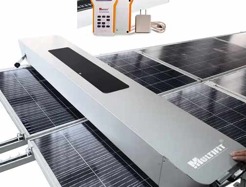
    Shadows should be paid attention to in the design and installation of photovoltaic power plants, and more attention should be paid to later operation and maintenance. For long-term operation of photovoltaic power generation systems, dust accumulation on panels has a great impact on power generation efficiency. The dust on the surface of the panel has the functions of reflecting, scattering and absorbing solar radiation, which can reduce the transmittance of the sun, resulting in a decrease in the solar radiation received by the panel, and the output power is also reduced, and its effect is proportional to the accumulated thickness of dust. Common shadows mainly include bird droppings, dust, tree shade, buildings, fallen leaves and branches, etc. At present, there are three cleaning methods for photovoltaics: human working, water wheel cleaning and robot cleaning. 1.      Characteristics of human working Hard to manage, inefficient, and long hours. The cleaning process affects power generation. The cleaning quality is difficult to guarantee, and there are safety risks and large losses in operation. 2. Water wheel cleaning The cleaning range is limited, and it is only suitable for ground power stations with sufficient space and free entry and exit of vehicles. It won't do anything with rooftop photovoltaic panels, desert power stations, or tightly packed power stations. 3. Robot cleaning Regular cleaning, significantly increased power generation, night work, no impact on power generation, more than 50 times more efficient than human working, self-powered, self-storage, no external energy, unattended, intelligent control, no water cleaning, no waste of water resources.
1 2 3

A total of3pages

Need Help? Chat with us

Our hours
Mon 11/21 - Wed 11/23: 9 AM - 8 PMThu 11/24: closed - Happy Thanksgiving!Fri 11/25: 8 AM - 10 PMSat 11/26 - Sun 11/27: 10 AM - 9 PM(all hours are Eastern Time)
Submit
Contact us #
+86 -18655186412

Our hours

Mon 11/21 - Wed 11/23: 9 AM - 8 PM
Thu 11/24: closed - Happy Thanksgiving!
Fri 11/25: 8 AM - 10 PM
Sat 11/26 - Sun 11/27: 10 AM - 9 PM
(all hours are Eastern Time)

Home

Products

whatsApp

contact