Analysis of changes and causes of lithium battery capacity attenuation!
Sep 21, 2024
1. Analysis of lithium-ion battery capacity attenuation
Positive and negative electrodes, electrolytes and diaphragms are important components of lithium-ion batteries. The positive and negative electrodes of lithium-ion batteries undergo lithium insertion and extraction reactions respectively, and the amount of lithium inserted in the positive and negative electrodes becomes the main factor affecting the capacity of lithium-ion batteries. Therefore, the balance of the positive and negative electrode capacities of lithium-ion batteries must be maintained to ensure that the battery has optimal performance.
2. Overcharge
2.1 Negative electrode overcharge reaction There are many types of active materials that can be used as negative electrodes of lithium-ion batteries, with carbon-based negative electrode materials, silicon-based, tin-based negative electrode materials, lithium titanate negative electrode materials, etc. as the main materials. Different types of carbon materials have different electrochemical properties. Among them, graphite has the advantages of high conductivity, excellent layered structure and high crystallinity, which is more suitable for lithium insertion and extraction. At the same time, graphite materials are affordable and have a large stock, so they are widely used.
When a lithium-ion battery is charged and discharged for the first time, solvent molecules will decompose on the graphite surface and form a passivation film called SEI. This reaction will cause battery capacity loss and is an irreversible process. During the overcharging process of a lithium-ion battery, metal lithium deposition will occur on the negative electrode surface. This situation is prone to occur when the positive electrode active material is excessive relative to the negative electrode active material. At the same time, metal lithium deposition may also occur under high rate conditions.
Generally speaking, the reasons for the formation of metal lithium leading to the change in lithium battery capacity decay mainly include the following aspects: first, it leads to a decrease in the amount of circulatory lithium in the battery; second, metal lithium reacts with electrolytes or solvents to form other by-products; third, metal lithium is mainly deposited between the negative electrode and the diaphragm, causing the pores of the diaphragm to be blocked, resulting in an increase in the internal resistance of the battery. The influencing mechanism of lithium-ion battery capacity decay varies depending on the graphite material. Natural graphite has a high specific surface area, so the self-discharge reaction will cause the lithium battery capacity loss, and the electrochemical reaction impedance of natural graphite as the negative electrode of the battery is also higher than that of artificial graphite. In addition, factors such as the dissociation of the negative electrode layered structure during the cycle, the dispersion of the conductive agent during the production of the pole piece, and the increase in the impedance of the electrochemical reaction during storage are all important factors that lead to the loss of lithium battery capacity.
2.2 Positive electrode overcharge reaction Positive electrode overcharge mainly occurs when the proportion of positive electrode material is too low, resulting in an imbalance in the capacity between the electrodes, causing irreversible loss of lithium battery capacity, and the coexistence and continuous accumulation of oxygen and combustible gases decomposed from the positive electrode material and the electrolyte may bring safety hazards to the use of lithium batteries.
2.3 Electrolyte reacts at high voltage If the charging voltage of the lithium battery is too high, the electrolyte will undergo an oxidation reaction and generate some by-products, which will block the electrode micropores and hinder the migration of lithium ions, thereby causing the cycle capacity to decay. The change trend of the electrolyte concentration and the stability of the electrolyte is inversely proportional. The higher the electrolyte concentration, the lower the electrolyte stability, which in turn affects the capacity of the lithium-ion battery. During the charging process, the electrolyte will be consumed to a certain extent. Therefore, it needs to be supplemented during assembly, resulting in a reduction in battery active materials and affecting the initial capacity of the battery.
3. Decomposition of electrolyte The electrolyte includes electrolytes, solvents and additives, and its properties will affect the service life, specific capacity, rate charge and discharge performance and safety performance of the battery. The decomposition of electrolytes and solvents in the electrolyte will cause the battery capacity to be lost. During the first charge and discharge, the formation of SEI film on the surface of the negative electrode by solvents and other substances will cause irreversible capacity loss, but this is inevitable. If there are impurities such as water or hydrogen fluoride in the electrolyte, the electrolyte LiPF6 may decompose at high temperatures, and the generated products will react with the positive electrode material, resulting in the battery capacity being affected. At the same time, some products will also react with the solvent and affect the stability of the SEI film on the surface of the negative electrode, causing the performance of the lithium-ion battery to decay. In addition, if the products of the electrolyte decomposition are not compatible with the electrolyte, they will block the positive electrode pores during the migration process, resulting in battery capacity decay. In general, the occurrence of side reactions between the electrolyte and the positive and negative electrodes of the battery, as well as the generated by-products, are the main factors causing battery capacity decay.
4. Self-discharge Lithium-ion batteries generally experience capacity loss, a process called self-discharge, which is divided into reversible capacity loss and irreversible capacity loss. The solvent oxidation rate has a direct impact on the self-discharge rate. The positive and negative active materials may react with the solute during the charging process, resulting in capacity imbalance and irreversible attenuation of lithium ion migration. Therefore, it can be seen that reducing the surface area of the active material can reduce the capacity loss rate, and the decomposition of the solvent will affect the storage life of the battery. In addition, diaphragm leakage can also lead to capacity loss, but this possibility is low. If the self-discharge phenomenon exists for a long time, it will lead to the deposition of metallic lithium and further lead to the attenuation of the positive and negative electrode capacities.
5. Electrode instability During the charging process, the active material of the positive electrode of the battery is unstable, which will cause it to react with the electrolyte and affect the battery capacity. Among them, structural defects of the positive electrode material, excessive charging potential, and carbon black content are the main factors affecting battery capacity.
 Liquid Cooling vs Air Cooling for ESS Energy Storage System: High-Rate Performance vs Low-Cost Solutions
Apr 21, 2026
Liquid Cooling vs Air Cooling for ESS Energy Storage System: High-Rate Performance vs Low-Cost Solutions
Apr 21, 2026
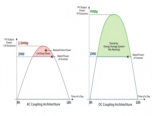 How to Select DC Coupling & AC Coupling in Solar Energy Storage System?
Feb 06, 2026
How to Select DC Coupling & AC Coupling in Solar Energy Storage System?
Feb 06, 2026
 Anti-Islanding Protection in Solar PV Systems
May 12, 2025
Anti-Islanding Protection in Solar PV Systems
May 12, 2025
 How to Choose the Right Solar PV System: Residential vs. Commercial
Jan 16, 2025
How to Choose the Right Solar PV System: Residential vs. Commercial
Jan 16, 2025
 Solutions to low insulation impedance for "PV insulation impedance is too low"
Jan 02, 2025
Solutions to low insulation impedance for "PV insulation impedance is too low"
Jan 02, 2025